Quantcast
Channel: Reviews Archives - The DXZone
Viewing all 50 articles
Browse latest View live

Icom IC PW-1

$
0
0

ICOM logoWide frequency coverage with 1 KW output

All HF bands plus 50 MHz are covered. The IC-PW1 provides a stable, clean and low distortion 1 kW from 1.8 MHz to 50 MHz*. In addition, full duty cycle (even during more demanding RTTY or SSTV operation) and full break -in operation are possible. Great for DX’peditions or contest operation.


Wide ALC adjustable range

Internal circuitry allows the ALC to be adjusted over a wide range. This means that the IC-PW1 can be used with almost any HF, 6 m or HF/6 m rigs – not only Icom rigs

Compact body

Dimensions, including amplifier, power supply, tuner and controller, are only 350(H) x 269(W) x 378(D)mm* And, because the controller is detachable, the IC-PW1 can be installed almost anywhere in your shack.

Other outstanding features

  • Automatic antenna tuner built-in
  • Automatic AC input voltage selector is employed
  • Current (Ip), Voltage (Vp), temperature, SWR and output power protectors are available

ICOM IC PW-1 links

from our Icom IC-PW1 link category

DX4Win and Icom PW-1
Using DX4WIN with ICOM radios and the ICOM PW-1 RF power amplifier...

Icom PW-1 Linear Amplifier
Official web site of Icom PW-1 KW linear amplifier at icomamerica.com...

Icom PW-1 repair notes
Repairing instruction of the Icom PW-1 amplifier to solve the issue where the red protection LED comes on with SEND and the b...

Controlling the PW-1 Amplifier
Configuring dxlab commander to properly control the Icom PW-1 power amplifier...

Icom IC-PW1 Specifications
The Icom IC-PW1 is a 1000 watt linear amplifier with built-in power supply...

The post Icom IC PW-1 appeared first on The DXZone.


Radio Frequency Interference (RFI) Pocket Guide

$
0
0

Radio Frequency Interference (RFI) Pocket Guide

by Kenneth Wyatt, WA6TTY – Michael Gruber, W1MG
Scitech Publishing , July 2015

ISBN: 978-1-61353-219-5

RFI Pocket GuideThis small 88-page spiral bound (3” x 5”) pocket guide is written primarily for radio amateurs and others in the radio communications field having to deal with RFI problems.

It would also be helpful to homeowners, or anyone, trying to troubleshoot RFI and TVI problems in home entertainment equipment (radios, TVs, and stereo equipment).

It makes a good companion to “The ARRL RFI Book,” the editor of which, Michael Gruber, is also a co-author of this guide.

The other co-author of this guide, Ken Wyatt, also authored the “EMC Pocket Guide” with Randy Jost.

The Radio Frequency Interference Pocket Guide starts with a discussion of some fundamental EMC principles, includes a frequency versus wavelength table, and lists broadcast frequency allocations in the U.S.

This is followed by the crux of the material in four sections (40 pages):

  • Identifying RFI
  • Locating RFI
  • Resolving RFI
  • Assembling an RFI Locator Kit.
Identifying RFI

Interference is characterized as either narrow band or broadband. The vast majority of RFI is caused by either unintentional RF emission from consumer devices, or ac power line noise. The switched-mode power supplies used to power consumer devices are a very common source of broadband radio frequency interference. This is also true of other switching devices such as the newer LED lighting devices. Power line noise caused by arcing on electric power lines is another relatively common broadband interference source. Less common narrowband noise sources are also covered, such as two-way mobile radio, paging transmitters, broadcast transmitters (AM, FM, and TV), and cable television system cable leakage.
The authors make the important point that, “you don’t need to know what it is [the source of the noise] in order to find it.”

Locating RFI

This I believe is the most important sections of the Pocket Guide. It gives detailed procedures for tracking down or localizing the source of the RFI. I once found a defective incandescent light bulb (arcing inside of the bulb) that was causing interference to my TV using a method very similar to that described in this guide. The authors also detail procedures for determining if the noise source is inside or outside of your home and discusses simplified direction finding techniques.

Resolving RFI

Having found the source, or location, of the noise, the next step is to resolve the interference problem. The use of ferrite chokes and filters are discussed. The guide also gives useful tips on dealing diplomatically with neighbors, when the source of interference is found to be located on their property. In some cases you may want to get some additional local help from the ARRL, FCC, or the local power company. For example, if ac power line arcing is involved, you will have to get the power company involved with the fix. Most power companies are more than happy to do this if you can point out to them where the problem is.

Assembling an RFI Locating Kit

This section discusses specific equipment that can be used in tracking down an RFI problem, from simple and inexpensive (portable AM or AM/SW broadcast receivers), to professional equipment (spectrum analyzers and radio receivers). One feature of this guide that I really like is that it gives specific details, model numbers, and in many cases prices, for the recommended test equipment. This section also includes a list of RFI mitigation components (ferrites, filters, copper tape, etc.) that may be required to solve the problem.


The guide ends with a listing of references and other resources including FCC and European Union EMC regulations, commonly used equations, books, magazines, useful web sites, standards organizations, as well as a listing of manufactures and distributors of test equipment and mitigation components.


This handy Pocket Guide contains a lot of useful information. It outlines in very concise form the procedures necessary for tracking down most radio frequency interference problems. For anyone wanting to track down an RFI problem, without having to learn all the basic theory involved, this Pocket Guide is a valuable resource. For those interested in learning more details about RFI problems, the Pocket Guide in combination with a more in-depth text, such as the aforementioned “ARRL RFI Book” would make a good combination.

Review By:

Henry W. Ott
Henry Ott Consultants
Livingston, New Jersey

The post Radio Frequency Interference (RFI) Pocket Guide appeared first on The DXZone.

ICOM IC-7200

$
0
0

ICOM logo

The Icom IC-7200 is a robustly built amateur transceiver providing coverage of HF amateur bands plus 6 meters. Power is 100 watts. Features include easy-to-use controls, DSP filtering with 51 passband widths, digital twin passband tuning, manual notch filter, keypad entry, dual VFOs, large display, voice synthesizer, 201 memories, 20 dB attenuator, preamp, 6 kHz roofing filter, RIT, scanning, 1 Hz step tuning and more! The excellent general coverage receiver tunes from 30 kHz to 60 MHz. The meter displays Power/SWR/ALC. Power is 2 to 100 watts (40 watts AM).

Although the IC-7200 is not waterproof, extra design steps have been applied to the front panel buttons and knobs. This provides a measure of protection against water intrusion. There is even a USB port on the rear panel! This radio comes with an HM-36 hand mic, OPC-1457 DC power cord and spare fuses.

IC-7200 Specifications
 
General
  • Frequency Range:
    • RX 0.030-29.999999 MHz (guaranteed range: 0.5-29.999999 MHz)
    • TX 1.800-1.999999 MHz, 3.500-3.999999 MHz (varies with version)
    •   5.3305, 5.3465, 5.3665, 5.3715, 5.4035 *2
    • 7.000-7.300000 MHz, 10.100-10.150000 MHz
    • 14.000-14.350000 MHz, 18.068-18.168000 MHz
    • 21.000-21.450000 MHz, 24.890-24.990000 MHz
    • 28.000-29.700000 MHz, 50.000-54.000000 MHz
  • Mode: USB, LSB, CW, RTTY (FSK), AM
  • No. of memory channels: 201 (199 regular, 2 scan edges)
  • Frequency resolution: 1 Hz
  • Frequency stability: Less than ±0.5 ppm.
  • Power supply requirement: 13.8 V DC ±15% (negative ground)
  • Current drain (at 13.8 V DC):
    • Receive: stand-by 1.3 A ; max audio 2.0 A
    • Transmit: max. power 22.0 A
  • Usable temperature range: -10°C to +60°C (+14F to+140F)
  • Antenna connector: SO-239 (50 ohm)
  • Dimensions: 240mm (W) x 95mm (H) x 239mm (D)
  • (projections not included) 9 7/16in (W) x 3 3/4in (H) x 11 1/16in (D)
  • Weight: 5.5 kg; 12.1 lb
  • ACC connector: 13-pin
  • REMOTE connector: 2-conductor 3.5 (d) mm; (1/8″)


Transmitter
  • Modulation system:
    • SSB: Digital PSN modulation
    • AM: digital low power modulation
  • Output power:
    • SSB, CW, RTTY: 2-100W
    • AM: 1-40W
  • Spurious emissions: Less than -50 dB below peak output power
  • spurious freq.; below 30 MHz: -50dB, above 30 MHz: -63dB
  • Carrier suppression: More than 50 dB
  • Unwanted sideband: More than 50 dB
  • Microphone connector: 8-pin connector (600 ohm)
  • KEY connector: 3 conductor 6.5 (d) mm (1/4″)
  • SEND connector: Phono (RCA)
  • ALC connector: Phono (RCA)


Receiver
  • Receiver system: Triple-conversion superheterodyne
  • Sensitivity: (10 dB S/N)
    • SSB, CW, RTTY: 0.16 µV (1.8-29.999999 MHz)
    • AM: 13 µV (0.5-1.799999 MHz)
    • AM: 2 µV (1.8-29.999999 MHz)
  • SQL sensitivity: Less than 5.6 µV (SSB)
  • Selectivity:
    • SSB, CW, RTTY: More than 2.4 kHz/-6 dB
    • Less than 3.6 kHz/-60 dB
    • AM: More than 6.0 kHz/-6 dB
    • Less than 16 kHz/-60 dB
  • Spurious and image rejection ratio: More than 70 dB (1.8-29.999999 MHz)
  • Audio output power: More than 2.0 W at 10% distortion with at 8 ohm load (at 13.8 V DC)
  • RIT variable range: ±9.9 kHz
  • PHONES connector: 3-conductor 6.5 (d) mm (1/4″)
  • EXT SP connector: 2-conductor 3.5 (d) mm (1/8″) 8 ohms
  • Specifications are subject to change without notice or obligation.

The post ICOM IC-7200 appeared first on The DXZone.

Baofeng BF-UVB2 Plus

$
0
0

Baofeng BF-UVB2 Plus

VHF UHF Handheld transceiver

The new dual band U/V transceiver from Baofeng cover VHF 136-174 MHz and UHF 400-520 MHz and feature a 68-108 MHz FM receiver.

Comes in four different colors, and offers a total of 128 memories, and a power output of 5 W Max.

Among other relevant features, the new Baofeng BF-UVB2 Plus feature, battery saving function, a programmable keyboard and a VOX function along to the Dual-Watch and Crossband reception.

Default configuration includes a 1800 mah Li-ion battery and a  Dual BaBaofeng UV B2Plus VHF UHFnd antenna, Belt Clip, Desktop Charger and an Earpiece.

Total radio weight is under 130g and dimensions 58mm x 110mm x 32mm

Baofeng BF-UVB2  Price is approx 40 USD.

Browse our Ham Radio Shops category

Here a Review and test of the Baofeng UBV2 Plus, listed in our Youtube Channel


The post Baofeng BF-UVB2 Plus appeared first on The DXZone.

Radio Direction Finder DF2020T

$
0
0

DF2020T Radio Direction Finder kit requires minimum assembly for 10~15 Minutes

The Stealth DDF2020T/GPS is an economical but very sophisticated Doppler Direction Finder with GPS and can connect a PC or Laptop, to position and draw plots on GoogleEarthTM display window accompanied with “Navi 2020” plotting program.

FUNCTIONS

  • Multi Display – Numeric & 36 LED pelorus display
  • Compatible with APRS software
  • Can use with “Navi2020” map plotting display program (with the optional GPS Receiver)
  • Uses GoogleEarthTM viewer for displaying map of ploiting.
  • Automatic or manual operation
  • Accepts standard $GPRMC NMEA GPS message
  • Archive Navi files are auto-saved

GLOBAL_TSCM_GROUP__INC__-_Radio_DF_DDF2020T 2Banners_and_Alerts_e_GLOBAL_TSCM_GROUP__INC__-_Radio_DF_DDF2020T

Radio Direction Finder DF2020T

The post Radio Direction Finder DF2020T appeared first on The DXZone.

Alpin 200

$
0
0

ALPIN LogoThe linear amplifier Alpin 200 is designed for all HF amateur bands from 1,8 – 29,7 Mhz.

It is equipped with pair metal – ceramic tetrode 4CX-800A (GU-74B).

The Alpin 200 contains a build in microprocessor which monitors all important parameters and show them to the LCD display. It realize also protection system, which can avoid damages.


Technical Specifications

  • Frequency coverage: All Amateur Radio Bands 1.8-29,7 MHz
  • Power output: 2000 Watts continous
  • Output Circuit: Pi-L Network with matching Capability – VSWR up to 1:3 (15-160 Ohms)
  • Output impedance: 50 Ohm unbalanced
  • Input circuit: Broadband with VSWR less than 1.3:1
  • Driving power: 60 Watts (typical)
  • Harmonics suppression: > 50dB
  • Intermodulation distortion: > 35dB
  • RF gain: 15dB
  • Primary power: 230VAC – 50/60Hz
  • Tube: Pair 4CX800A (GU74B) forced air
  • Dimensions: (W x D x H) 470mm x 415mm x 190mm
  • Weight: 40 kg


The post Alpin 200 appeared first on The DXZone.

CQ DX Zones World Map

$
0
0

Icom is the publisher of the free to download, double-sided world map showing the CQ DX Zones and the ITU Zones.

Each map uses an Albers Equal Area projection and feature a color-coded ITU regions and a complete list of country codes that include ham radio prefix call, country name and latitude and longitude. This map  can be easily downloaded and printed in a large A3 format. It serves as an illustrative tool to help you in any DX adventure!

Information listed in this map is current as of February 2013.

Visit and download other Amateur Radio Map Sites
Read our article on 15 Best Ham Radio Map Sites

The post CQ DX Zones World Map appeared first on The DXZone.

COMET CAA-500 MKII

$
0
0
COMET CA 500 MKII
COMET CA 500 MKII

COMET CAA-500 MKII

Frequency range: 1.8-500MHz
Graphic and Analog Displays
Analog cross needle display of SWR and total impedance for quick antenna checks and adjustments

TFT LCD graphic display provides graphic and numerical SWR and impedance info simultaneously with the analog display

AUTO-SWEEP mode

Graphs SWR in pre-determined Amateur Band frequency ranges in seconds

MANUAL-SWEEP mode

Manually graph the SWR curve after you set the desired bandwidth MULTIPLE

MANUAL-SWEEPS: Overlay up to 5 manual sweeps in 5 selectable colors as you make antenna location or length adjustments

Operates on 8-16VDC external power or 6AA alkaline or NiMH batteries • Trickle charger built in ( NiMH only) • Battery indicator light • Selectable auto power off time limit • SO-239 for the 1.8- 300MHz range • N-female for 300-500MHz

CAA-500MarkII_Eng_ver1_pdf

The post COMET CAA-500 MKII appeared first on The DXZone.


TEN-TEC RX-340 Commercial Monitor Receiver

$
0
0

Ten-TecThe TEN-TEC RX 340 is a multi mode, general coverage synthesized receiver utilizing extensive Digital Signal Processing.

DSP brings the performance and repeatability of expensive military grade communications receivers into the price range of top end commercial receivers for shortwave listeners.

Tunable from 5 kHz to 30 MHz, it provides tuning steps and display resolution of 1 Hz. All three displays are blue green vacuum fluorescent and provide unparalleled contrast and readability.

The RX 340 is a laboratory quality instrument in its ability to quantify the amplitude and frequency characteristics of signals and receivers.

The post TEN-TEC RX-340 Commercial Monitor Receiver appeared first on The DXZone.

SunSDR2 PRO

$
0
0

SunSDR2 PRO

Expert ElectronicsThe Expert Electronics SunSDR2 PRO is a compact HF to VHF Transceiver with a modern design.

Max HF Power is 15 W, reduced to 7 W in VHF. Receiver architecture is based on 16 bit DDC (digital down conversion) with a 14 Bit DUC (Digital Up Conversion) used in TX.

External connections includes, a 100 Mb/s LAN Ethernet port, Wi-Fi (optional), Jacks for Phones and Microphone, plus an additional Yaesu standard Mic 2 socket.

Antenna connection is via two mini-UHF connectors for HF and an additional one for VHF.
The back of the radio includes also two standard Jack connections for a Morse key and external PTT control.

Price 2110 USD

Sun SDR 2 Pro Sun SDR 2 Pro Rear

SunSDR2 Pro Specifications

General coverage receiver

0.09 to 65MHz and 95 to 148MHz

Frequency coverage, HF Tx

All amateur bands

Frequency coverage, VHF Tx

144 to 146MHz

Sensitivity μV

0.07μV

Maximum Tx power HF

15W

Maximum Tx power VHF

7W

Blocking dynamic rage, HF

129dB

Blocking dynamic range, VHF

>114dB

ADC clock frequency/ resolution

160MHz/16-bit

DAC clock frequency/resolution

640MHz/14-bit

Power supply

12 to 16 volts, 15V recommended at 5A

Dimensions

165 x 165 x 35mm

Weight

1kg


SunSDR2 Pro Brochure

SunSDR2 Video

The post SunSDR2 PRO appeared first on The DXZone.

MetroVNA Antenna Analyzer

$
0
0

MetroVNA Antenna Analyzer

Modern antenna analyzer designed for amateur radio by IZ7LDG

The MetroVna Pro is a commercial Vector Network Analyzer enables the user to perform measurements of antennas, filters, cables and much more independent from a location. The frequency range of the MetroVna Pro starts at 1 MHz and goes up to 180 MHz, covering most major amateur radio bands from 160 to 2m (VHF). The backlit colour display is easy to read for all measurements and serves as an input device as well, because of the touch function.

The softkeys on the display change according to the setting and mode and offer a clear and easy to understand handling of the device. In addition to the display keys a row of conventional keys placed on the solid metal case are available as well.

MetroVNA allows you to measure all the parameters of an antenna as SWR, R, X, Z,Phase,RL,TL and produce graphics on the color display, or PC, tablet, smartphone.

MetroVNA is a powerful and simple test equipment to use both outdoors and in the laboratory.

Allows measurements both in transmission and in reflection mode, and has a complete multi platform software capable to run under  Windows, Linux, MacOSX and even Android.

MetroVNA has many useful features including an easy menu for quick measurements and graphs and a menu to control basic parameters.

MetroVNA Antenna Analyzer Features

  • Fast USB interface
  • Instrument is run by a powerful 32-bit microprocessor.
  • Designed for use in amateur radio
  • Many functions can be easily activated from the menu.
  • Over 10 internal menus upgradeable by firmware.
  • Include internal Li-ion rechargeable battery.
  • Full touch screen display.

Technical Features MetroVna Pro Touch 180 MHz

  •  Coverage 1/180 MHz 160/2mt
  •  Measure R,Z,X (no sign),SWR,TL,|Phase|,ReturnLoss
  •  Exit DUT -6dBm su 50ohm
  •  Max signal imput –70/+5dBm
  •  Accuracy +-2dB
  •  Operating voltage 3.3V
  •  Dimensions 125mm x 95mm x 20mm
  •  Weight 200gr

Functional characteristics

  •  Display TFT 3.1” 16 K color touch screen
  •  Ten Menu + four service menu
  •  Internal Rechargeable Battery LI-ion 5000mAh
  •  Battery charging circuit
  •  Interface USB / Wireless technology
  •  updating Firmware USB
  •  compatible with IG/VNA, VNA/J , BluVNA and more
  •  Compatible with Tablet,Smarthphone Android
  •  Platforms SW WIN,LINUX,ANDROID,MAC
Antenna Analyzer MetroVNA Antenna Analyzer Metro VNA Antenna Analyzer Metro VNA Vector Antenna Analyzer

Official MetroVNA Web Site

Current Price: 330 Euro

The post MetroVNA Antenna Analyzer appeared first on The DXZone.

Alinco DX-10

$
0
0

AlincoAlinco DX-10 10 Meter Amateur Radio with SSB AM FM CW Modes

The Alinco DX-10 is a multimode mobile transceiver that provides access for new radio amateurs to the 10 meter band. It is also useful for the seasoned operator looking for a simple, inexpensive mobile transceiver.

Alinco DX-10 Alinco DX-10 Alinco DX-10 Alinco DX-10

The Alinco DX-10 is a capable, compact, multimode 10 meter transceiver. It will operate in LSB, USB, AM, FM or CW modes. Operation is from 28-29.7 MHz. Power output is adjustable (0-25W SSB and 1-12W FM/AM/CW). This radio does not employ a traditional VFO. Rather, frequencies may be stored in the expansive memory system and then adjusted by the fine tuning.

The meter can display S/RF, SWR or DC voltage. Scanning is supported. The radio features SWR and power supply voltage protection.

Tuning steps may be set to 10 Hz, 100 Hz, 1 kHz or 10 kHz. This radio requires 13.8 VDC at 6 amps.
The DX-10 includes the EMS-70 Hand Mic (with metal plug), mobile bracket, DC cord and mounting hardware.

Features

  • AM / FM / USB / LSB / CW / PA Modes
  •  Multiple Clarifier Operating Modes
  • Flexible Menu Functions
  • Echo and Tone Controls
  • RF Gain Adjustment
  • Variable RF Power Adjustment
  • Scan Function
  • Roger Beep
  • Noise Blanker / Automatic Noise Limiter
  • Dual Watch Function
  • +10 KHz Button
  • SWR, S/RF, DC Voltage Display
  • Hi-Cut Function
  • Cutoff for high frequency interference

Specifications

  • Frequency Range : 28.000MHz~29.700MHz
  • Operating Mode : SSB/CW/AM/FM
  • Frequency Resolution :10Hz, 100Hz, 1kHz, 10kHz
  • Channels : Up to 60ch per Bank (6 Banks)
  • Antenna Impedance : 50 ohm unbalanced
  • Frequency stability : +/-1ppm
  • Microphone Impedance : 2k ohms
  • Power supply requirement : 13.8V DC +/-15% (11.7 to 15.8V DC)
  • Operating Temperature : -22°F ~ +122°F (-30°C ~ 50°C)
  • Current (Approx.) : Transmit 6A Max
  • Dimensions: 6.7 in (w) x 2.04 in (h) x 8.4 in (d)
  • Output power:   FM/AM/CW 1-12 W    USB/LSB 0-25W

The post Alinco DX-10 appeared first on The DXZone.

AOR ARD 300 Multi Mode Digital Voice Decoder

$
0
0

Multi Mode Digital Voice decoder for analog receivers

AOR

The ARD300 decodes the following digital modes.

  • APCO 25 (P25) (Phase 1 conventional)
  • ICOM (R) D-STAR
  • NXDN (6.25kHz mode)
  • YAESU (R) (V/D mode)
  • ALINCO (R) (for EJ-47U only)
  • dPMR (dMPR446 and Tier 1 mode)

ARD300 Features

  • Versatile and powerful digital voice decoder/demodulator for your trusted analog receiver!
  • Decodes dPMR, NXDN and popular amateur digital voice mode from Icom, Alinco and Yaesu.
  • Decodes APCO P25 voice signals, used for example by U.S military and diplomatic services around the world.
  • Compatible with AOR legacy receivers AR8600MK2, AR5000(A/+3), AR-ONE and newer AR2300, AR5001D, AR6000.
  • Supports any other brand’s receiver featuring a 10.7MHz or 45.05MHz IF output!(*1)

AOR ARD300 Brochure


The post AOR ARD 300 Multi Mode Digital Voice Decoder appeared first on The DXZone.

Baofeng UV-5001

$
0
0

BTECH UV-5001 VHF/UHF Mobile 2-Way Radio

baofengtechWide Frequency Coverage The UV-5001 provides extended receiver coverage of 136-174Mhz and 400-520Mhz (beyond the Amateur bands), so you can keep informed of communication activities in the public safety, commercial, and government communications ranges. The UV-5001 is able to Transmit on Narrowband (12.5kHz) and Wideband (25kHz).


uv-5001-2-lg uv-5001-1-lg uv-5001-3-lg uv-5001-4-lg uv-5001-5-lg

Dual Watch Receiver The UV-5001 operates as two radios in one, with either 144 MHz or 430 MHz as the “Main” TX/RX band, while simultaneously watching the other band. And, if you like, you can configure your UV-5001 for VHF-VHF or UHF-UHF operation, too!


Simultaneous Display For those that want to have the most information at their fingertips on a specific channel – they can synchronize the displays. You can configure the displays to synchronize and allow both the Channel Name and frequency to simultaneously display on the selected channel.

High Power Output To get your message through when it counts, the UV-5001 puts out 50 Watts of power on the VHF band, and 45 Watts on UHF.


Group Tones supportedThe UV-5001 supports the most common Analog Tones. It supports CTCSS, DCS, 2 Tone, 5 Tone, Voice Inversion, and DTMF calling methods. Set-up your calling methods to call by group tones. Tone calling (private line) is required by most repeater applications and the UV-5001 supports the latest standards.

The UV-5001 can even send DTMF tones. This allows for sending ANI (Caller ID) or remote commands that require DTMF tones; or it can receive incoming DTMF tones to allow for remote stun or kill commands

Fully Customizable through the Free Software You can program your UV-5001 exactly how you want it. There are 200 programmable memory channels. You can add or remove channels from scanning list. You can give channels alphanumeric names. The radio has an available low power setting of 10 watts, allowing you to choose how far you can communicate. You can easily program from a PC to set-up the radio to operate exactly as needed. (The PC04 FTDI Cable is recommended for easy programming)

UV-5001 Price 

From the BTECH Online store BTECH UV-5001 price is approx 150 USD

UV-5001 Features

  • 25KHz/12.5KHz Switchable (Wide/Narrow Band)
  • FM Radio (65.0MHz-108.0MHz)
  • Large Tri-color LCD Display (3 Selectable Colors)
  • High /Low RF Power Switchable
  • 50 CTCSS/ 104 DCS Tones
  • 5Tone Support
  • 2Tone Support
  • Voice Inversion (Scrambling) Support
  • Tone searching/scanning
  • Dual standby
  • PC programmable
  • Transmitter time-out timer(TOT)
  • Busy channel lock-out(BCLO)
  • Remote Stun/Kill

UV-5001 MOBILE SPECIFICATIONS

  • Frequency range: [TX] 136 – 174MHz, 400 – 520MHz [RX] 136 – 174MHz, 400 – 520MHz, 68-108MHz (FM Broadcast)
  • Channel Capacity:  200 Channels
  • Channel Spacing 25KHz (wide band)12.5KHz (narrow band)
  • Sensitivity  ≤0.25μV (wide band) ≤0.35μV (narrow band)
  • Operation Voltage  13.6V DC ±20%
  • Frequency step:  2.5-25KHz Selectable
  • Antenna: Antenna Connector: SO-239
  • Stability:  ±2.5ppm
  • Output power:  50W / 10W
  • Audio Power Output   1000mW/10%

Baofeng UV-5001 English Manual

The post Baofeng UV-5001 appeared first on The DXZone.

ICOM IC-7300 Brochure

$
0
0

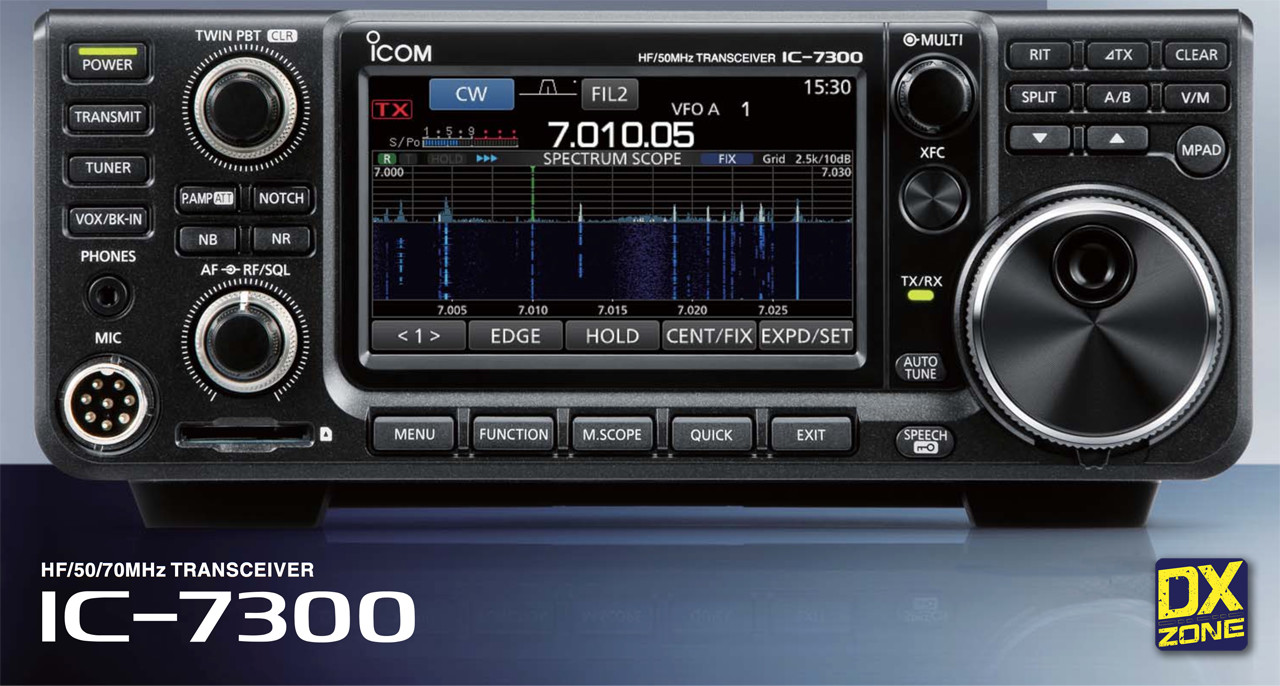
IC-7300 – The Innovative HF Transceiver with High Performance Real-Time Spectrum Scope

Class Leading Real-Time Spectrum Scope

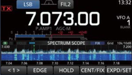
The IC-7300’s real-time spectrum scope is class-leading in resolution, sweep speed and dynamic range. While listening to received audio, you can check the real-time spectrum scope and quickly move to an intended signal. When you first touch the scope screen around the intended signal, the touched part is magnified. A second touch of the scope screen changes the operating frequency and allows you to accurately tune.

IC-7300 Spectrum Scope

Real-Time Spectrum Scope Specifications

  • Scope system:FFT (Fast Fourier Transform)
  • Sweep Speed: Max. 30 frames/second (approx.), Selectable from slow, mid or fast
  • Span width:  5kHz–1000kHz
  • Resolution:  1 pixel minimum (approximately)
  • Waveform display area (vertical axis) : 80dB
  • Reference level adjustment: –20dB to +20dB
  • Peak level hold function (Max. hold): ON/OFF/last 10 seconds
  • Averaging indication
  • Touch screen operation
  • VBW (Video Band Width) adjustment

 High-Resolution Waterfall Function

Spectrum scope + Waterfall

The combination of the waterfall function and the real-time spectrum scope assists in maximum receive performance of the IC-7300 and increases QSO opportunities without missing weak signals. The waterfall function shows a change of signal strength over a period of time and allows you to nd weak signals that may not be apparent on the spectrum scope.

FFT scope/Oscilloscope

Audio Scope Function

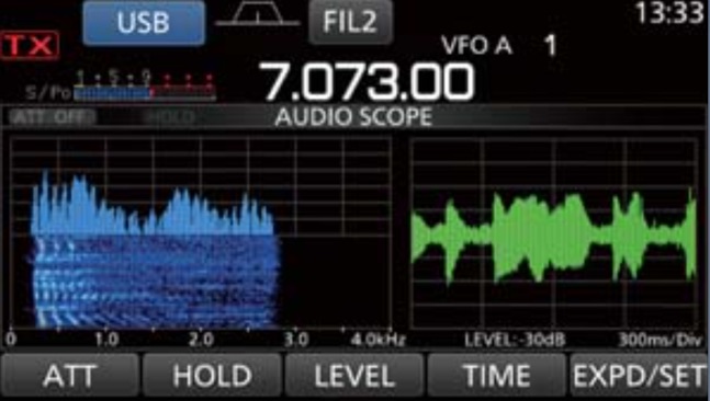
The audio scope function can be used to observe various AF characteristics such as microphone compressor level, filter width, notch filter width and keying waveform in the CW mode. Either the transmit or receive audio can be displayed on the FFT scope with the waterfall function and the oscilloscope.

ICOM IC-7300
ICOM IC-7300
IC-7300 Rear Panel View

RF Direct Sampling System

The IC-7300 employs an RF direct sampling system. RF signals are directly converted to digital data and processed in the FPGA (Field Programmable Gate Array), making it possible to simplify the circuit construction. This system is a leading technology making an epoch in amateur radio.

IC-7300 RF Direct Sampling System

New “IP+” Function

The new “IP+” function improves 3rd order intercept point (IP3) performance. When a weak signal is received adjacent to strong interference, the AD converter is optimized against signal distortion.

Class Leading RMDR (Reciprocal Mixing Dynamic Range) and Phase Noise Characteristics

The IC-7300’s RMDR is improved to about 97dB* (typical value) and Phase Noise characteristics are improved about 15dB (at 1 kHz frequency separation) compared to the IC-7200. The superior Phase Noise characteristics reduce noise components in both receive and transmit signals.

IC-7300-RMDR and Phase-Noise
IC-7300 Touch Screen

Large Touch Screen Colour TFT LCD

The large 4.3 inch colour TFT touch LCD offers intuitive operation. Using the software keypad of the touch screen, you can easily set various functions and edit memory contents.


IC-7300 multi dial knob
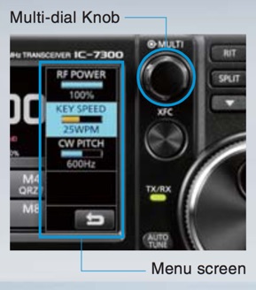
Multi Dial Knob

Multi-Dial Knob for Smooth Operation

The combination of the multi-dial knob and the touch screen offers quick and smooth operation. When you push the multi-dial knob, menu items are shown on the right side of the display.
You can select an item with a touch of the screen and adjust levels by turning the multi-dial knob.

IC.7300 Filters
IC-7300 Filters

15 Discrete Band-Pass Filters

The IC-7300 has 15 discrete RF band-pass filters.
The RF signal is only passed through one of the band-pass filters, while any out of range signals are rejected.
High Q factor coils are used to minimize the loss in the RF band-pass filters

Built-In Automatic Antenna Tuner

Antenna Tuner IC-7300
IC-7300 Antenna Tuner

The antenna tuner memorizes its settings based on your transmit frequency, so that it can rapidly tune when you change operating bands. The Enforced Tuning function allows a wide range of temporary antennas to be tuned.

Superior Sound Quality

To offer superior sound quality, a new speaker unit has been incorporated and is allocated dedicated space in the aluminum die-cast chassis.

SD Memory Card Slot for Saving Data

The IC-7300 can store various contents into SD card such as received and transmitted audio, voice memories, RTTY/CW memories, RTTY decode logs and captured screen images. Personal and firmware updating data can also be stored to the SD card for easy setting.

Other Features

  • New HM-219 hand microphone supplied
  • Effective large cooling fan system
  • A Multi-function meter
  • 101 memory channels (99 regular, 2 scan edges)
  • Optional RS-BA1 IP remote control software (the spectrum scope with the waterfall can be observed)
  • CW functions: Full break-in, CW reverse, CW auto tuning

IC-7300 Specifications

IC-7300 Specifications

IC-7300 Price

Currently price is around 1450 Euro / 128,000 JPY  (Mid Jan 2016)

IC_7300-Price
IC-7300 Price via Google Search – Sold by MHZ Elettronica in Italy

Link to Ham Radio Shops

Download the IC-7300 english borchure

The post ICOM IC-7300 Brochure appeared first on The DXZone.


Yaesu FT-891

$
0
0

Yaesu FT-891Yaesu Logo at dxzone.com

HF/50 MHz 100 W All Mode Transceiver

  • Rugged construction in an ultra compact body 6.1″ x 2.0″ x8.6″ (155x52x218 mm)
  • Stable 100 W Power Output with efficient Dual Internal Fans
  • Legendary Yaesu Receiver Design
  • Triple conversion with a 1st IF frequency of 69.450 MHz
  • 3 kHz roofing filter equipped as standard
  • Detachable front panel for convenient mounting and operation
  • Large dot matrix LCD display with Quick Spectrum Scope
  • Ease of Operation
    • Large diameter Main Tuning Dial (1.6″ / 41mm) with Torque adjustment
    • Pop-up Menu for quick and easy operation
    • Multi Function Knob
    • Large Transmit / Receive indicator
    • Three Programmable Front Panel Function Keys
  • Specifically designed External Antenna Tuner FC-50 (option)
  • Support Active Tuning antenna systems (ATAS-120A, ATAS-25 Option)
  • USB port allow connection to a PC with a single cable (CAT, PTT, RTTY)
Yaesu FT891
Yaesu FT 891

100 W Reliable High Power Output

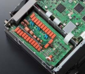
The FT-891 provides stable 100 W (25 W AM) high power output. High reliability is assured by the transmitter careful circuit design with efficient thermostatically-controlled dual internal fans and the diecast chassis.

FT-891 RearIF DSP provides effective and optimized QRM rejection

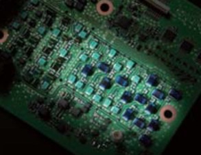
The 32 but high speed floating point DSP (max 3000 MIPS) provides effective cancellation/reduction (DNR) of the random noise that is frequently frustrating in the HF frequencies. Also the AUTO NOTHC (DNF) automatically eliminates the dominant beat tone. The CONTOUR and the APF are very effective receiver noise reduction tools in the HF bands operations. The YAESU original DSP QRM and noise reduction functions are provided.

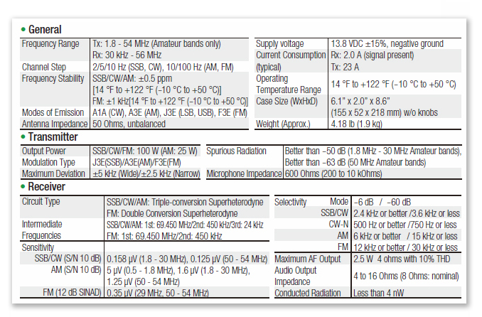
Yaesu FT-891 Specifications


The Yaesu FT-891 has been approved by the F.C.C.
FT-891 Price and availability not yet defined.
Technical specifications may be subject to change.

The post Yaesu FT-891 appeared first on The DXZone.

RS-918SSB HF SDR Transceiver

$
0
0

Recent RS-918SSB

Quanzhou Risen Electronics Co., Ltd

The Chinese Recent, Quanzhou Risen Electronics Co. Ltd, manufacturer of Digital and Analog transceivers, recently released the RS-918SSB a QRP HF SDR Transceiver working all HF Ham Radio Bands, with a maximum output power of 15W, in SSB, CW, AM (RX only), FM and FreeDV.

The compact dimensions 215×74×62mm and the weight of 623g make it an interesting transceiver for portable operations.

RS-918SSB Main Features

  • Spectrum Dynamic Waterfall Display
  • Multiple Working Modes: Receive,Transmit,Tune,VFO,SPLIT
  • DSP Digital Signal Processing Noise Reduction
  • Automatic Notch Filter
  • Humanized Interface Color Display
  • Receive Fine Tuning Function, Changeable MIC Gain Value
  • VCC Power Supply Voltage Indication Table
  • Transmit Signal Strength Display Table
  • Multifunctional Instrument: SWR Meter, AVD Audio Frequency Meter, ALC Signal Modulation Meter

RS-918SSB Technical Specifications

  • Frequency Range – RX: 1.8-30MHz  TX:All HAM HF BANDS
  • Operating Mode – SSB(J3E),CW,AM(RX Only), FM, FREE-DV
  • TX Power – 5W (Standard, DC 13.8V) , 15W (Full,DC 13.8V)
  • Receiving Sensitivity – 0.11~0.89μV (RFC 50-20)
  • Minimum Frequency Step – 1Hz
  • Operating Voltage – DC9~15V
  • Antenna Impedance – 50Ω
  • Frequency Stability –  ±1.5PPM @ Power on 5 Minutes (Standard) ; ±0.5PPM if Optional TCXO Used
  • Product Dimension (W × H × D) – 215×74×62mm(Mounting Bracket Included)
  • Weight – 623g

RS-918SSB Price

According to Larry Yang of Quanzhou Risen Electronics Co. Ltd, the RS-918SSSB is sold at USD 350 + Shipping Costs.

Click to view slideshow.

RS-918SSB Videos

Notes

As far as we know the RS-918SSB is based on the well known mcHF QRP transceiver project originally designed by Chris M0NKA.

The post RS-918SSB HF SDR Transceiver appeared first on The DXZone.

DAV FCA1000 HF+50 MHz Power Amplifier

$
0
0

FCA 1000 Solid State HF+6MT Amplifier

The FCA1000 is a new RF Power Amplifier designed for the Amateur Radio bands by DAV, an Italian electronic company.

DAV FCA1000

1250 W SOLID STATE HF + 6 MT AMPLIFIER

Technical Specifications

  • Frequency coverage: All HF Bands (including WARC and 60 Meters) + 6 meters
  • Power output: : 1250W constant output power from 160 to 6 meters
    • Switchable in 4 steps (200W,500W,1000W,1250W)
  • Antennas: 3 Antenna outputs
  • Antenna Tuner: Built-in ATU matching up to 500 Ohms
  • Display and Controls:  Full colour, high resolution, touch screen display
  • Interfaces:
    • CAT interface for RTX and PC
    • PC software to set and configure the amplifier
    • ALC and Relay Interfaces can automatically detect used frequency
    • Network Interfaces: Wi-FI and LAN interface
    • PC Interfaces: Bluetooth and two USB ports
    • Built-in web server to display in a mobile device all running settings
  • Dimensions : 32x16x40cm  13x6x16 inch
  • Weight: 9 Kg – 20 lb
  • Primary power: 230VAC – 50/60Hz

The amplifier has been recently presented during the Ham Fest in Montichiari Italy, and will be distributed starting from December 2017, by the Italian radio dealer Ham Radio Shop.

The post DAV FCA1000 HF+50 MHz Power Amplifier appeared first on The DXZone.

AA-30 Analyzer by RigExpert a powerful antenna analyzer

$
0
0

RigExpert AA-30

rigexpert-logo

RigExpert AA-30 is a powerful antenna analyzer designed for testing, checking, tuning or repairing antennas and antenna feedlines.

Mainly, these are SWR (Standing Wave Ratio) and impedance measurement instruments (vector impedance analyzers).

Easy-to use measurement modes, as well as additional features such as connection to a personal computer (to plot Smith charts, etc.), make RigExpert AA-30 attractive for professionals and hobbyists. It is quite important that graphical display of various parameters over a wide frequency range is a key feature of these analyzers which significantly reduces the time required to adjust an antenna.

The following tasks are easily accomplished by using RigExpert AA-30:

Rapid check-out of an antenna
Tuning an antenna to resonance
Antenna SWR and impedance measurement and comparison before and after specific event (rain, hurricane, etc.)
Making coaxial lines or measuring their parameters
Cable testing and fault location
Measuring capacitance or inductance of reactive loads

Specifications

Frequency range: AA-30: 0.1 to 30 MHz, AA-54: 0.1 to 54 MHz

Frequency entry: 1 kHz resolution

SWR measurement range: 1 to 10
SWR measurement for 50 and 75-Ohm systems
SWR display: numerical or easily-readable bar
R and X range: 0-1000, -1000-1000 in numerical mode, 0-200, -200-200 in graph mode

Display modes:
– SWR at single or multiple (AA-54 only) frequencies
– SWR, R, X, Z, L, C at single frequency
– SWR graph, 100 points
– R, X graph, 100 points

RF output:
– Connector type: UHF (SO-239)
– Output signal shape: rectangular, 0.1-10 MHz (AA-30)
– Output power: about +13 dBm (at 50 Ohm load)

Power:
– Two 1.5V, alcaline batteries, type AA *
– Two 1.2V, 1800-2700 mAh, Ni-MH batteries, type AA *
– Max. 3 hours of continuous measurement, max. 2 days in stand-by mode when fully charged batteries are used
– When the analyzer is connected to a PC or a DC adapter with USB socket, it takes power from these sources

Interface:
– 128×64 graphical backlit LCD
– 6×3 keys on the water-proof keypad
– AA-30:menus and help screens in English language
– USB connection to a personal computer

Dimensions: 22X10X3.6 cm (9X4X1.5″);

Operating temperature: 0-40 C (32-104 F)

Weight (including batteries): 400g (14 Oz)


The post AA-30 Analyzer by RigExpert a powerful antenna analyzer appeared first on The DXZone.

Rigexpert AA-30.Zero

$
0
0

RigExpert AA-30.Zero

HF Antenna Analyzer

The AA-30.zero by RigExpert is a new DIY Antenna Analyzer component you

rigexpert-aa-30
Rigexpert AA-30.Zero

can use to build your own low cost arduino antenna analyzyer project, by integrating an arduino pcb, lcd display or even better a led display and the aa-30.zero.

.ZERO is even more powerful than the good old AA-30


RigExpert AA-30.ZERO

It is a standard AA-30 analyzer but without enclosure, LCD display and keypad.

But .ZERO is even more powerful than the good old AA-30.

Why is that ?

Creating AA-30.ZERO we met the numerous wishes of radio amateurs and DIY-hobbyists to give them a measuring tool that can be easily integrated into their own projects.

Are .ZERO ready for use?

Yes, it has everything necessary on board, so user can connect .ZERO to the PC (through USB-to-RS232 adaptor) and perform all the usual set of laboratory measurements.
.ZERO perfectly works with our AntScope software.

Want to DIY ?

Experienced user can pair .ZERO with the Arduino board making his own hardware/software project. Because .ZERO is compatible with Arduino standard.
Also we have already prepared examples of running .ZERO in the DIY projects.

Want to make your own automatic antenna tuner ? Use .ZERO!
Want to perform RF-circuits or antenna analysis remotely ? Pair .ZERO with the ESP8266 Wi-Fi SoM and do it!
Want to tune your antenna with driven elements sharply ? Use .ZERO to fine tuning.

Price & Power

It is not possible to find such an accurate and powerful analyzer at this price!
The dreams of radio amateurs will come true with this cheap and reliable device!

The AA-30.ZERO is intended for users who require flexibility, low-cost, and small size.
It comes without on-board USB or pin headers to keep the cost down.
It’s a best choice for a measuring core you want to leave embedded in a project.
Please note that the .ZERO operates at 5V (like most Arduino or Arduino compatible boards).
Be sure to provide the correct power and use components/adaptors whose operating voltage matches .ZERO.

Connecting .ZERO to the PC

The .ZERO comes without built-in USB circuitry, so an off-board USB-to-TTL serial convertor must be used to communicate with the .ZERO.
.ZERO communicates with external devices throug UART interface.
For these purposes two UART interfaces are provided: UART1 (pins 0/TX1 and 2/RX1) and UART2 (pins 4/TX2 and 7/RX2).
By default .ZERO uses UART2 interface.
To make our first project we could get, for example, the SparkFun USB UART Serial Breakout.

Specifications

Frequency range: 0.06 to 30 MHz
Frequency entry: 1 Hz resolution
Measurement for 25, 50, 75 and 100-Ohm systems

Housing: none
Display: 4 LED
Power supply: external
Communication interface: UART

SWR measurement range: 1 to 100 in numerical mode,
R and X range: 0…10000, -10000…10000 in numerical mode,
RF output
• Connector type: SMA, included, not mounted
• Output signal shape: square, 0.06 to 30 MHz
• Output power: +13 dBm (at 50 Ohm load)

Power
• Supply: External 5V
• Current consumption (max) 150 mA

General data
Dimensions (W x H x D) 55 mm x 69 mm x 5 mm (PCB only w/o connectors)
(2.1 in x 2.7 in x 0.2 in)
Weight 310 g (10.9 Oz) w/o connectors
Operating temperature 0…40 °C (32…104 °F)

NOTE: Specifications are subject to change without notice

Buy AA-30.Zero

Price of the AA-30.Zero antenna analyzer is aproximately uder the 90 USD.
Locate the RigExpert Dealer near you or buy Direct from RigExpert


AA-30.Zero demonstration

Learn how simple is to realize a low cost hf antenna analyzer in this video published by Alex UR4MCB.

The post Rigexpert AA-30.Zero appeared first on The DXZone.

Viewing all 50 articles
Browse latest View live